Main Page Sitemap Contact About this Website Data Privacy Deutsch


ultronics.de

^ < >

Explore 


   Software

  ==> TA 1069#Software


   Service Manual

  ==> Service Manual TA 1000


  Backplane

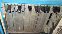
  The backplanes of  TA 1000 and TA 1069 are composed of slots with two
  different assignments.
  One assignment is used by the "Testtableau" (a type of hardware debugger)
  and for the CPU board, the second assignment is used for all remaining
  boards (ROM, RAM, I / O).
  Testtableau and CPU are located on the first two slots, the remaining slots
  are used by ROM, RAM and I/O boards, depending on the application
  in different compositions.
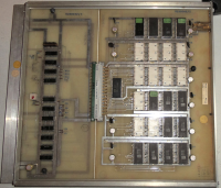
  In systems with two internal machines a backplane with two independent
  bus systems, arranged in a mirror image manner, is used - Testtableau
  and CPU occupy the first two and then the last two, of the usable slots.
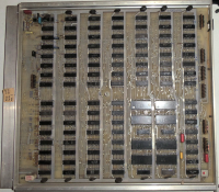
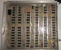
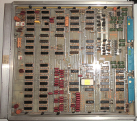
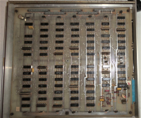
  ==> Circuit Diagram Backplane

TA1000 Unit
© Rainer Siebert Source


   Testtableau (PET 2)

  ==> Scanned orig. TA Circuit Diagram of Testtableau


   CPU-Board (AAB 01)

  TA 1000 and TA 1069 use the same CPU board.

  Otto Müller created with two SN7483AN- (4-bit adder), two SN7400N-,
  two SN7486N-,  four  SN7450N- and eight SN74H52N digital circuits
  an ALU,  with four SN7475N- and eight SN74100N latches a register file
  and with many other gates and other TTL circuits the necessary
  control unit, so that a total of 109 ICs (a 4-pin threshold switch
  included) form an 8-bit CPU with a 16-bit address bus.

  ==> Block Diagram of TA1000/TA1069 CPU
  ==> Searchable Circuit Diagram of TA1000/TA1069 CPU
  ==> Integrated Circuits of TA1000/TA1069 CPU
  ==> Scanned orig. TA Circuit Diagram of TA1000/TA1069 CPU
  ==> Micro Instruction Manual of TA1000/TA1069 CPU
TA1000 CPU
© Rainer Siebert Source


   ROM-Board (AAE 02)


TA1000 ROM
© Rainer Siebert Source


   RAM-Board (AAC 04)


TA1000 RAM
© Rainer Siebert Source


   CRT-Board


TA1000 CRT
© Rainer Siebert Source


   DFÜ-Board (AAN 11)

  ==> Scanned orig. TA Circuit Diagram of DFÜ-I/O-Board


   I/O-Board (AAG 31)


TA1000 I/O
© Rainer Siebert Source


   I/O-Board (AAS 03)


TA1000 FDC
© Rainer Siebert Source


   I/O-Board (AAM 11)

  ==> Scanned orig. TA Circuit Diagram of AAM-11-I/O-Board


© 2018 ultronics.de   Trademarks   Contact   About this Website   Data Privacy